Internships/ProjectIdeas/ArduinoVisualisation:detail: Difference between revisions
No edit summary |
No edit summary |
||
| Line 1: | Line 1: | ||
= QEMU emulated Arduino board visualizer = | |||
[[File:intended_arduino_visualization.png|800px|QEMU emulated Arduino board visualizer.]] | [[File:intended_arduino_visualization.png|800px|QEMU emulated Arduino board visualizer.]] | ||
The '''QEMU emulated Arduino board visualizer''' is a platform for QEMU based board emulation interfacing. | The '''QEMU emulated Arduino board visualizer''' is a platform for QEMU based board emulation interfacing. | ||
Using the inteface a board is defined as a group of *widgets* connected to the Ardunio. Each widget is defined as a block that can have two features: | Using the inteface a board is defined as a group of *widgets* connected to the Ardunio. Each widget is defined as a block that can have two features: | ||
| Line 40: | Line 41: | ||
[[File:ejecution_flow.png|800px|Execution flow.]] | [[File:ejecution_flow.png|800px|Execution flow.]] | ||
When the visualizer is run with a board a netlist is selected. The netlist is parsed by the app looking for the widgets used and generating a QEMU execution line. | == Visualizer == | ||
When the visualizer is run with a board a netlist is selected. Several netlist and visualization will be defined: | |||
* Board for Blink example: On/Off switch, LED wisget connected to GPIO. | |||
* Board for Fading example: On/Off switch, LED wisget connected to PWM output. | |||
* Board for Analog Input example: On/Off switch, LED wisget connected to GPIO, Potentiometer widget for blink control. | |||
== Netlist representation == | |||
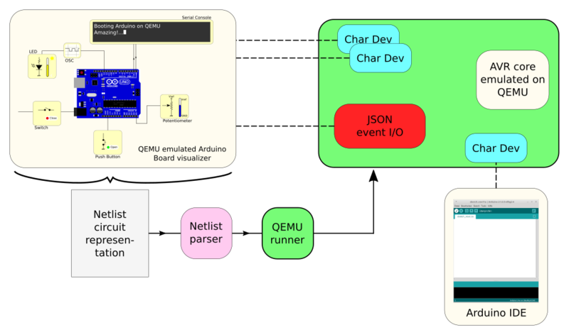
The netlist is parsed by the app looking for the widgets used and generating a QEMU execution line. | |||
== QEMU runner == | |||
The QEMU execution line will generate all the interface devices needed and will let ready the core for code execution. The app will use the interface devices generated by QEMU to update the visualizer and interact with the core. | The QEMU execution line will generate all the interface devices needed and will let ready the core for code execution. The app will use the interface devices generated by QEMU to update the visualizer and interact with the core. | ||
Once QEMU is running the Arduino IDE can be used to program the core and the interface to visualize/modify the board. | Once QEMU is running the Arduino IDE can be used to program the core and the interface to visualize/modify the board. | ||
Revision as of 10:29, 9 March 2020
QEMU emulated Arduino board visualizer
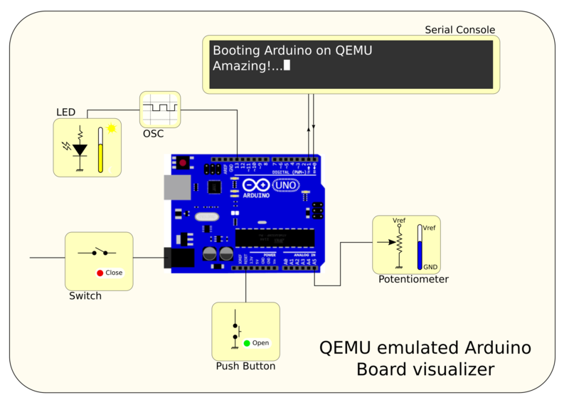
The QEMU emulated Arduino board visualizer is a platform for QEMU based board emulation interfacing.
Using the inteface a board is defined as a group of *widgets* connected to the Ardunio. Each widget is defined as a block that can have two features:
- User interaction: the user can modify the parameters of the widget.
- Visualization: the widget will show updates of the state of the circuit.
Widgets
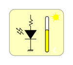
Led with brightness: the widget indicates the brightness of the led.
| |
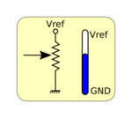
| Potentiometer: the widget modifies the middle point of the potentiometer configuring a variable voltage to the ADC. | |
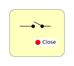
Switch: the widget will be used to turn on/off all the board. The state of the switch is represented with a colored box with text:
| |
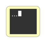
| Serial console: the widget will show the updated serial output. | |
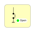
| Button: the widget could be modify by the user. While the button is pressed the pin is connected to GND and HiZ when not. | |
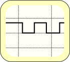
| Oscilloscope: the widget could be connected to any pin showing the updated signal generated by QEMU. |
Execution flow
Visualizer
When the visualizer is run with a board a netlist is selected. Several netlist and visualization will be defined:
- Board for Blink example: On/Off switch, LED wisget connected to GPIO.
- Board for Fading example: On/Off switch, LED wisget connected to PWM output.
- Board for Analog Input example: On/Off switch, LED wisget connected to GPIO, Potentiometer widget for blink control.
Netlist representation
The netlist is parsed by the app looking for the widgets used and generating a QEMU execution line.
QEMU runner
The QEMU execution line will generate all the interface devices needed and will let ready the core for code execution. The app will use the interface devices generated by QEMU to update the visualizer and interact with the core.
Once QEMU is running the Arduino IDE can be used to program the core and the interface to visualize/modify the board.

